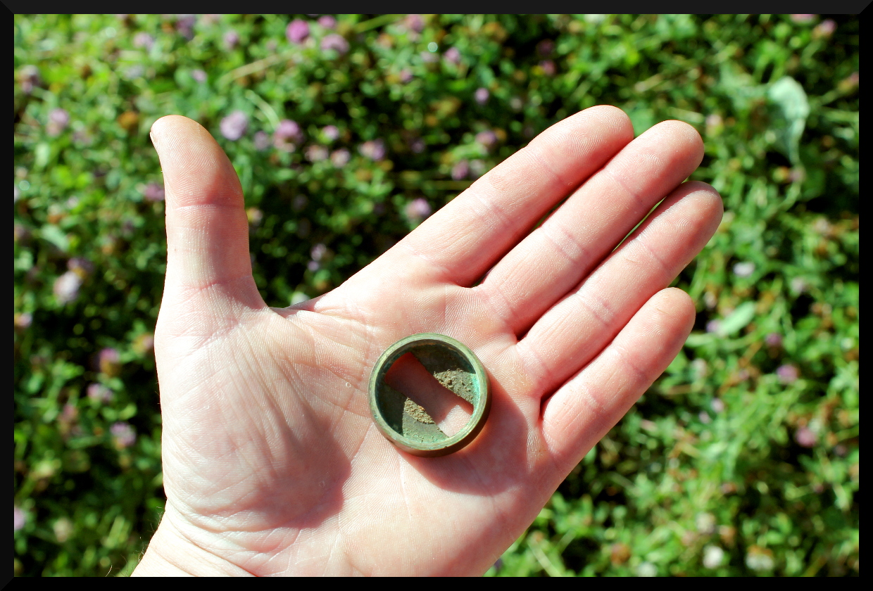
Just don’t. The only exception is when a blade’s heat treatment is way too soft AND you are absolutely certain that the blade is not laminated. Peen a laminated blade and the below will be the result.

Just don’t. The only exception is when a blade’s heat treatment is way too soft AND you are absolutely certain that the blade is not laminated. Peen a laminated blade and the below will be the result.
You’ve discovered that it has a few significant problems with it, right? Chances are the taper is noticeably irregular, the neck is as thick as a baseball bat, and you can’t get the nibs to loosen up despite knowing that they’re a left-handed thread because they were cranked on too tight at the factory. But here’s the good news: all of those issues are fixable.
The irregular taper and thick neck of the snath can be fixed with a little time with a spoke shave and rasp, and the nibs can be loosened by using some rubber vise jaw pads to hold the grips of the nibs tightly without marring or cracking them and using the shaft of the snath for leverage to break them loose. There’s one major flaw, however, that’s not as easy to correct…the collar is installed a whopping 20° out of alignment, and when the loop bolt is perpendicular to the ground like it should be, the arch of the snath is pointing right towards you.
It’s not a perfect fix, but you can correct for this by introducing a twist to the tang of your blade much like is commonly seen on European pattern blades. Heat the shank of the tang in same manner you would if you were adjusting its pitch, but instead, lock the tang in a sturdy vise and pull on the blade while the shank is still at heat to introduce a matching 20° twist to the tang. This will correct for the crooked collar to bring the arch of the snath back to vertical. The downside of this is that when adjusting the hang of your blade you’ll now be pivoting the length of the blade along a path that resembles an inverted cone instead of in a nice flat circle like you would with a snath that had the collar correctly mounted, but it’ll at least keep the arch from striking you in the thighs and knees every time you take a stroke with the scythe!


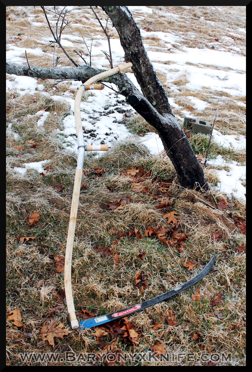
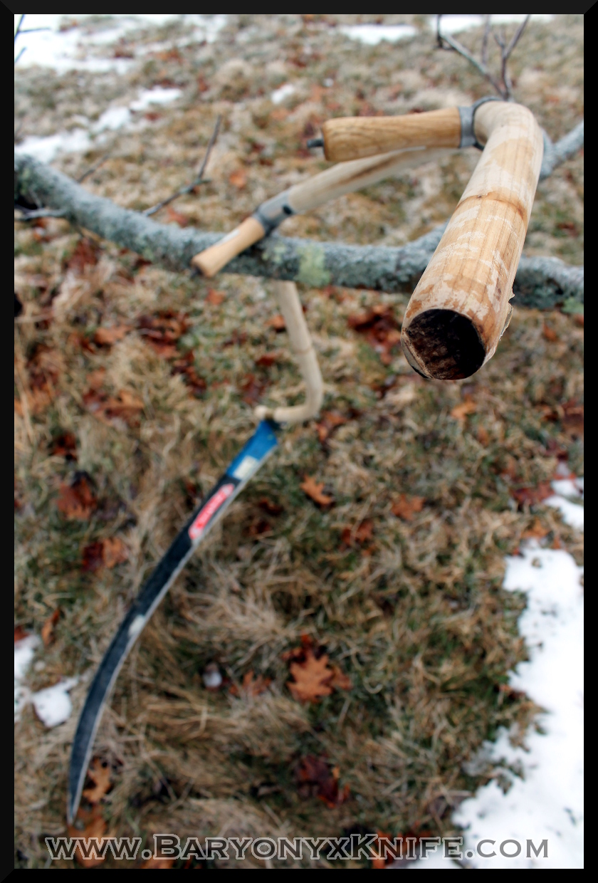
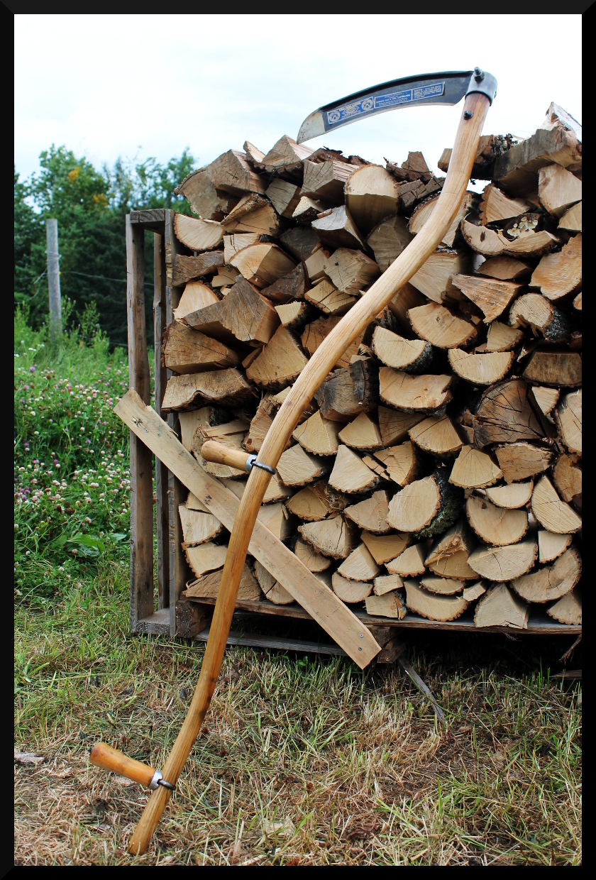
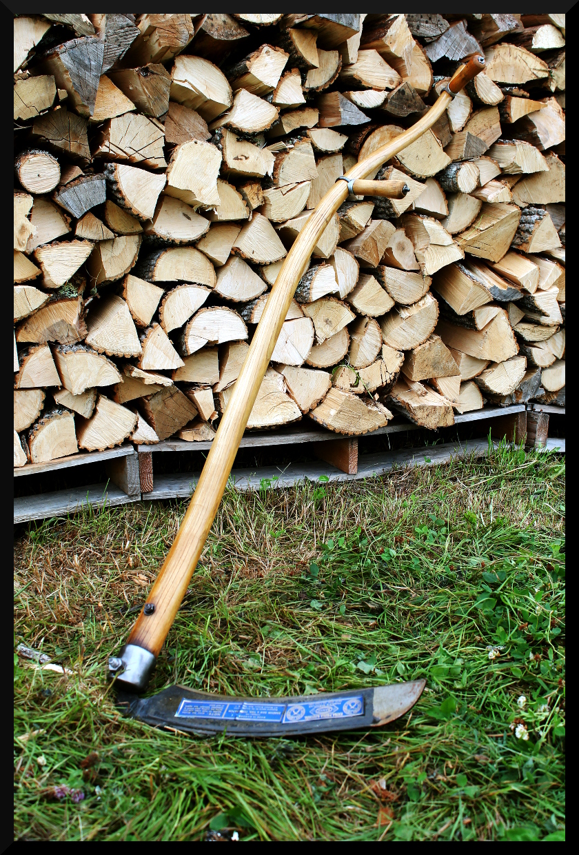
An initial proof of concept of the North Star snath. The snath is produced in two parts, and joined by an aluminum elbow. The halves in this case were both the same, but were technically both the upper half, as that was the component I received samples for. This resulted in too strong of a bend in the neck of the lower end, but the production version will have less severe of a curve.
The halves come overly long on purpose, allowing the user to trim them down to desired length. They can then be rotated in the aluminum coupling, allowing the snath to “shapeshift” to best adapt to the user’s preference before being drilled and bolted in its final position. This has the benefit of allowing for a truly one-size-fits-all scalable stemless snath, and allows the snath to pack down for transport or shipping. Note the strong lateral bend of the upper half. This both places the hand in a very ergonomic position, but the end can be used as a grip in its own right when lifting the lay of the blade while mowing, as circumstances sometimes dictate.


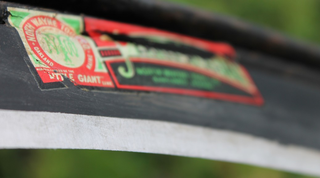
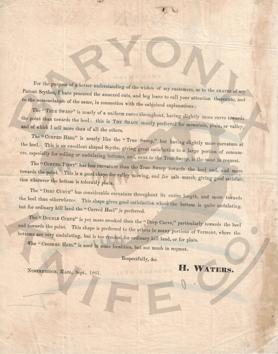
An illustrated brochure from scythe manufacturer Harvey Waters of Northbridge, Massachusetts, circa 1861, demonstrating his offered range of curvatures and describing their regional popularity for what kinds of terrain and growth. Mr. Waters has been credited with a number of manufacturing innovations, including the use of roll-forging as opposed to the typical use of trip hammers. A PDF form of this incredible document can be found HERE.

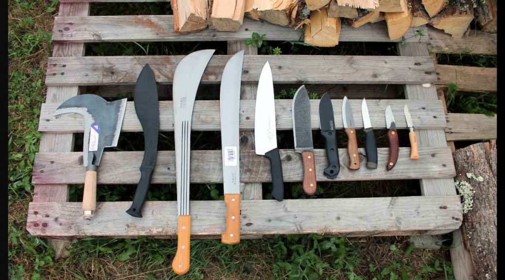
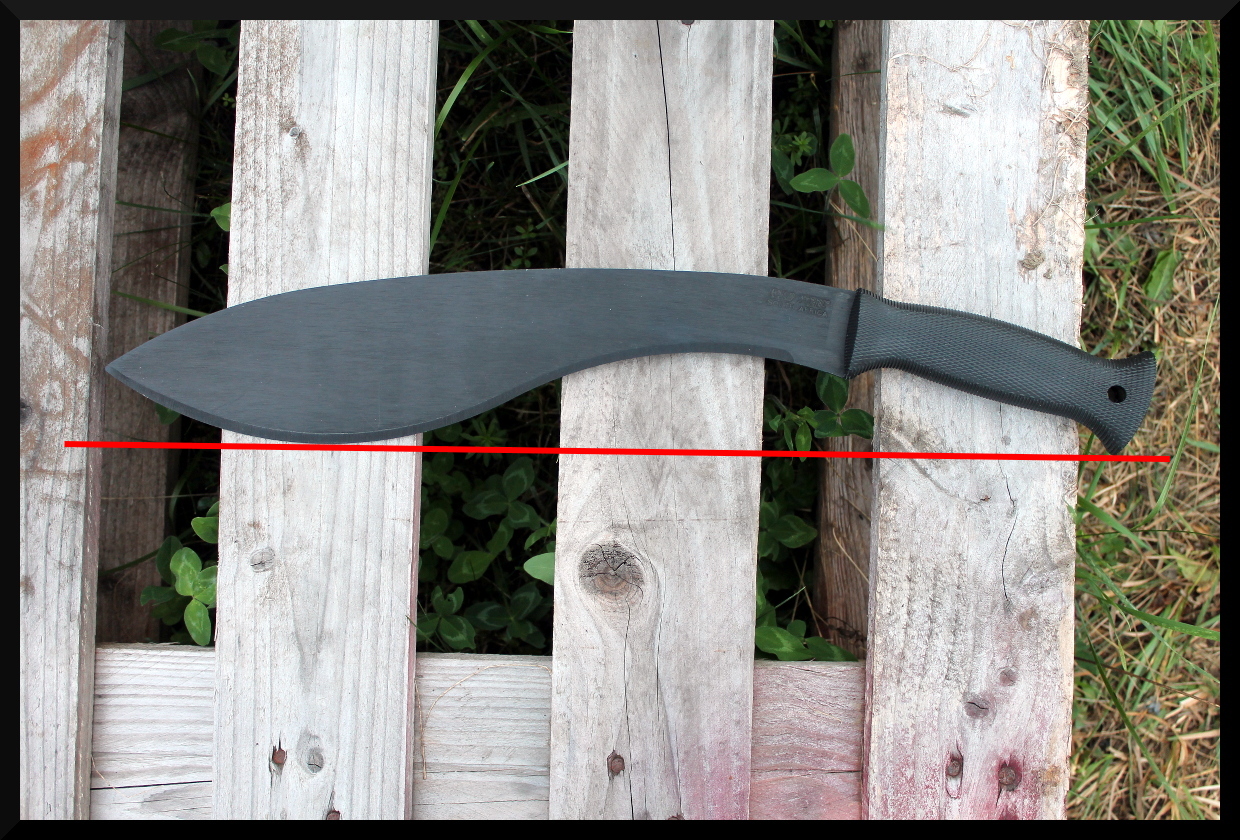
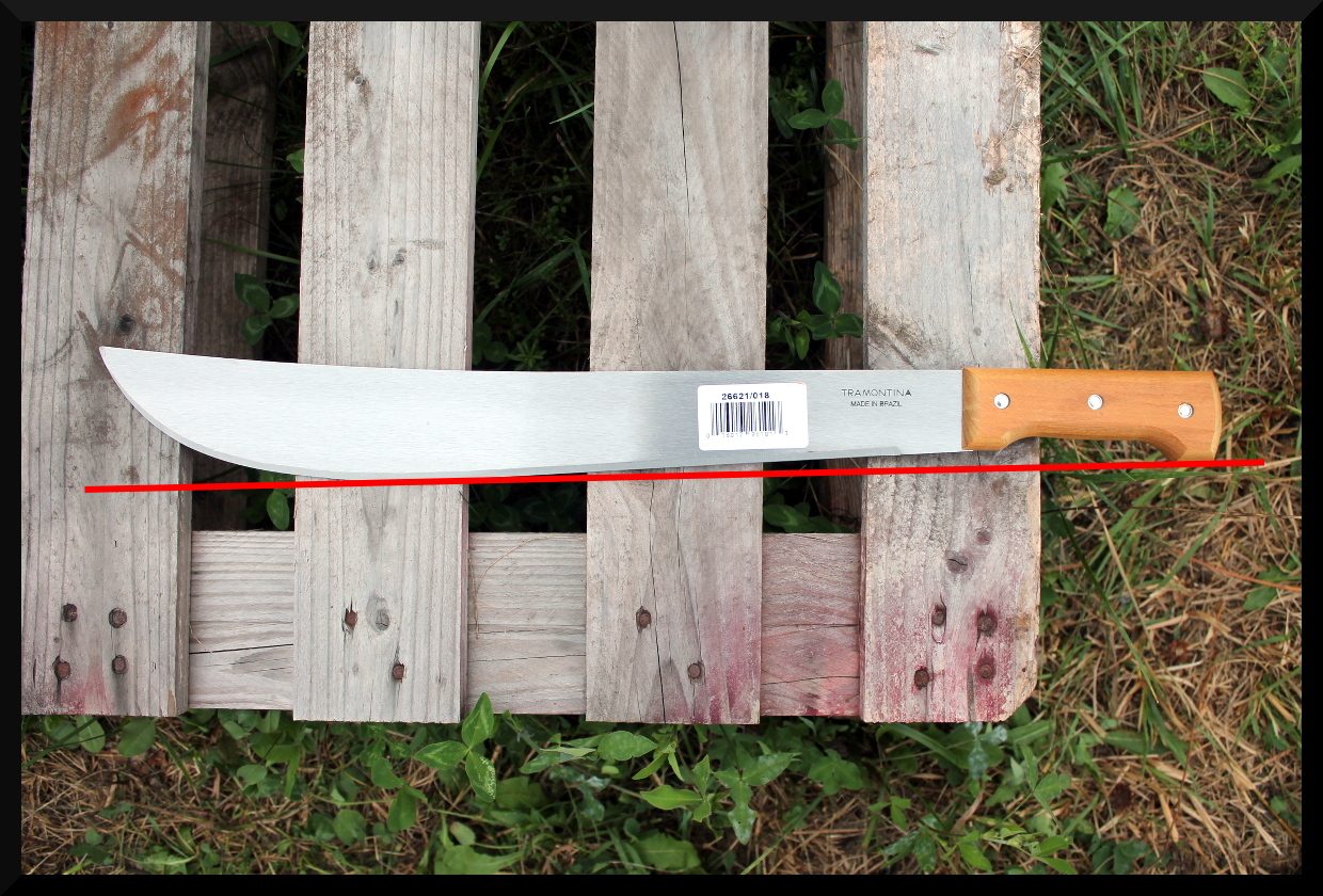
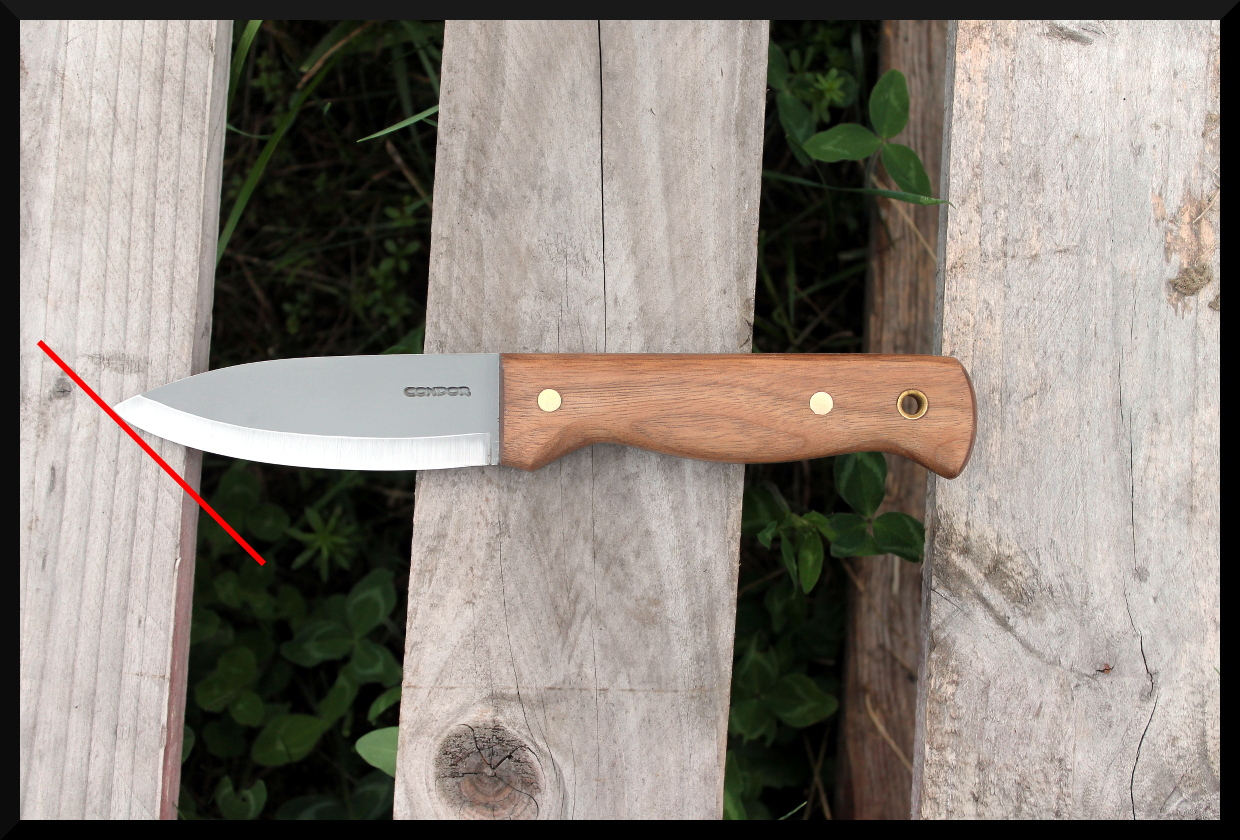
When analyzing knife and tool designs there are a wide range of approaches that can be used to develop an understanding of a particular tool’s ideal applications. One of these methods that I’m fond of using when initially sizing up a tool is the line test method. Imagining a superimposed straight line over various points of the tool’s outline is a quick and easy method for establishing rough concepts of tool clearance in use. That is to say, it helps you get an idea of how much space your hand will have in use, what regions of the blade will be making contact at what orientations relative to the target, and if any regions of the blade would be prevented from cutting against a broad flat surface. For instance, if you were cutting atop a chopping block of some kind, many forward curving blades would need to be chopping on a block of a certain height and width in order to deliver a blow along the interior of the blade’s arch without the hand striking the ground. To demonstrate this method, observe the differences between the following lineup when the test is applied.

To begin with, we’ll start the the most basic test–seeing what a line looks like describing a “table” surface, and what the tool would look like laying against it with one point of contact somewhere on the blade and one somewhere on the handle. This is the same as placing the tip of the blade on a table surface and rolling it back until the handle contacted it.


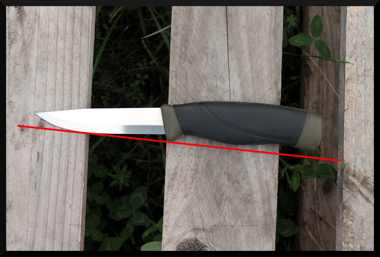


The line test can also be used to assess things like what part of the blade will be in contact with a surface when held at a given angle to it. This is often useful when considering specific task applications where the target will have a certain spacial relationship to the user. I often think of it in terms of if the target will be sitting above or below the elbow, and by how much. The following images show one example of the line test being used to approximate the angle at which the tip contacts the plane surface. However, if you have a particular set of tasks in mind for a knife, imagine the plane formed by a “line of best fit” by your targets and try using the line test at those angles to see if an appropriate region of the blade is being contacted.


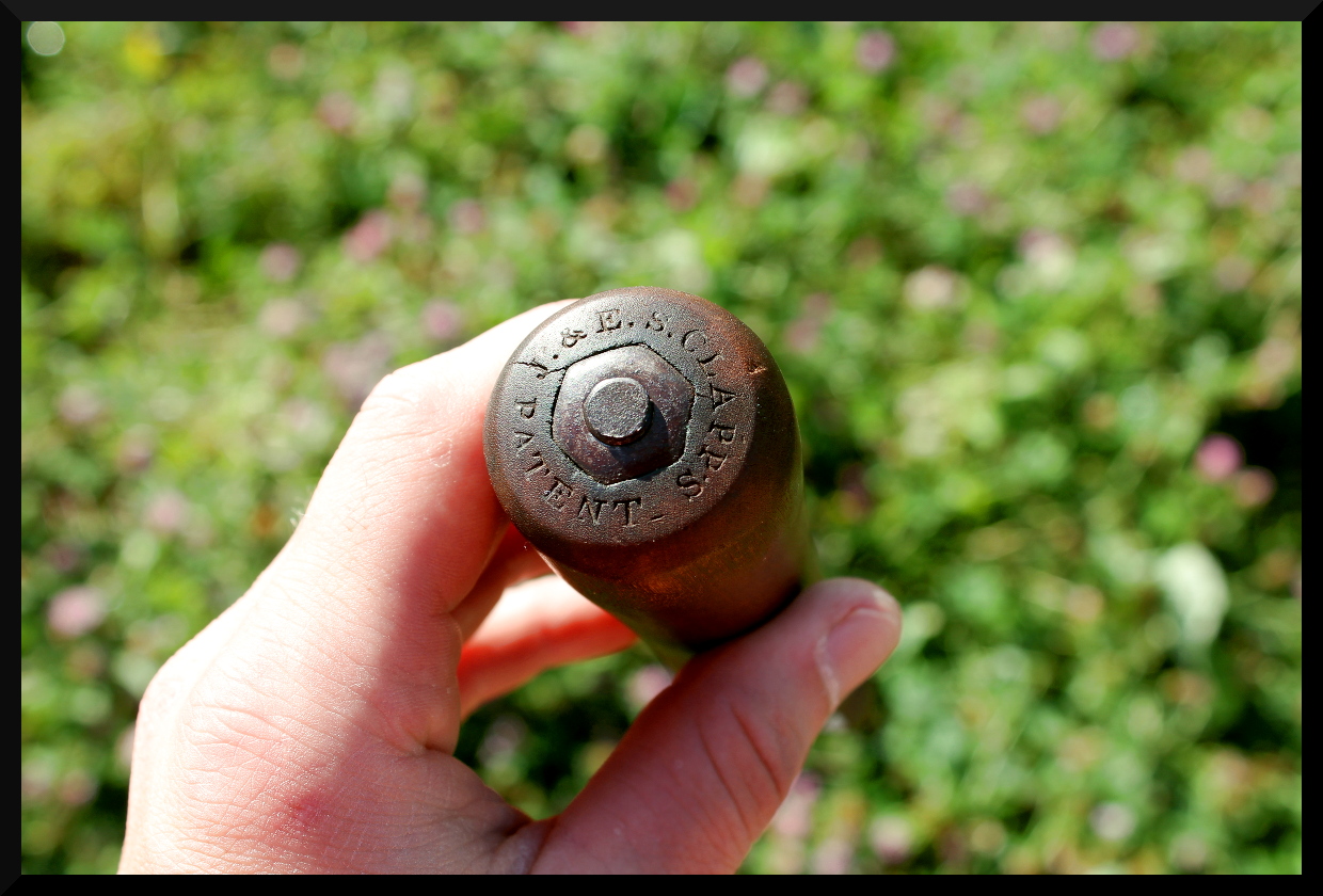
Up until the mid 19th century, American scythes had used the English method of affixing their nibs: an iron loop was fastened to the shaft of the snath by means of a wedge driven between the loop and the snath itself. While this allowed the nibs to be positioned at will along the snath, the wedges were prone to working their way loose at inconvenient moments, and in the industrial boom of the mid-1800’s a number of innovations were made in the means of fastening nibs. The most notable of these is the method that eventually became the standard: the so-called “Clapp’s Patent” nib. Patented in 1838 by Joseph and Erasmus S. Clapp of Montague, Massachusetts, it was the first nib known to bear the form that we see so commonly today on almost all snaths, both new and vintage. The nibs made currently by Seymour Midwest Tools are effectively of the same fundamental design.
We were fortunate enough to come into possession of an original example of one of Clapp’s Patent nibs, as well as a contemporary clone by Lamson Co. This company was particularly notable, for its owner and founder, Silas Lamson, is commonly credited with having inventing the steam bent curved snath as we know it today. This innovation is often cited as having been in 1834, though we have documentation that places it as much as 6 years earlier. An 1830 document declaring his letters patent include, among other innovations, “the mode of fastening the nibs without wedges” although we do not know the specific mechanism used. As can be seen in the following photos, our Lamson nib is nearly identical to the Clapp one. The Clapp patent seems to have been at the center of a court case regarding patent infringement in 1840.
See first the Clapp’s Patent example:


The Lamson Co. nib:


A professionally restored Seymour No.2 bush snath outfitted with a new old stock Swedish-made Banko bush blade. The Seymour No.2, now long discontinued, was similar to the still-produced No.1 grass snath but with a thicker end diameter and a four-hole heel plate rather than three. The holes are arranged in a “♦” shape rather than the “▼” arrangement on the No.1. Some older examples of this snath have capped nibs, with a three-pronged, domed, circular brad having been driven into the top of the nib to cover the recessed nut and projecting thread of the nib iron.


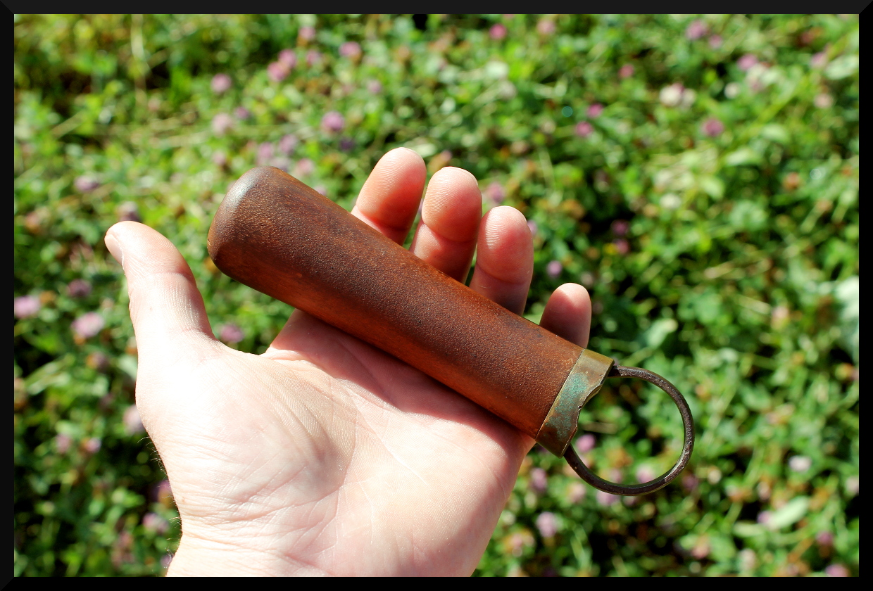
A traditional style of farm knife made from a broken American scythe blade, usually used for topping root crops.
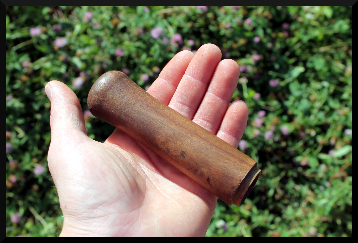
The blade below crack was cut back to the spine, which was forged out into a tang. Normally this would have been simply wrapped with rags to form the grip (which is why they were called rag knives) but we used a reshaped billhook handle instead.
The tang is peened on the end and the grip tightly wedged from the top inside the ferrule for an extremely tight and secure fit.


This is ideally what an American blade’s bevel should look like prior to honing. Note how far back the bevel goes, and its hollow form.